| Availability: | |
|---|---|
Application

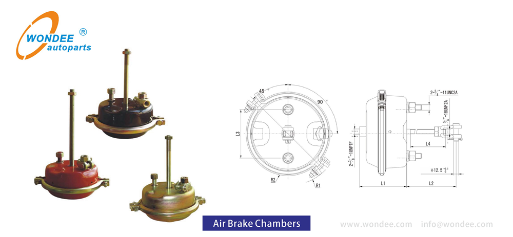
The brake air chamber is a device composed of an air inlet, a cover, a diaphragm, a support plate, a return spring, a housing, a push rod, a connecting fork, a clamp, and a bolt.
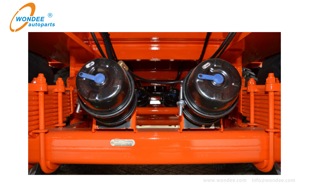
The brake air chamber is also called the brake cylinder. The function of the brake air chamber is to convert the pressure of the compressed air into the mechanical force that makes the brake camshaft rotate to realize the braking action. It is the executive element in the automobile air brake system and an important safety part on the automobile.
1. According to the function classification, there are single air chamber and double air chamber. The front and rear brake chambers of the dual air chambers are of different sizes, but their structures are basically the same.
2. According to the structure classification, there are membrane type and piston type. The brake air chamber is clamp clamping diaphragm type.
Features
| QC management system | Implementing IATF16949-2016 |
| Services quality management system | Implementing ISO9001-2015 |
| Product technical standards | SAE J14659 |
| Raw material | High strength steel material guarantee long-life pressure |
| Synthetic blended rubber diaphragms | Superior resistance against abrasion and fatigue cracking |
| Guided spring pressure plate | prevents side forces which cause diaphragm sidewall and seal wear |
| Special crimping method | ensures a no-guess diaphragm seal and allows for a low profile without clamp interference |
| Welding | CNC welding for push rod/plate attachment make it very strong |
| Painting | Treated and coated for corrosion protection, passes 200 hr salt spray test, to extend service life |
Comprehensive Info of brake chamber:
| Types | signal brake chamber, double brake chamber |
| Size | T9, T12, T16, T20, T22,T24, T27,T30, T12/16, T12/24, T14/16, T16/16, T16/24, T20/24, T22/24, T24/16, T2424, T2430, T3030. |
| Interchangeable brands (model) | JOST, Wabco, |
| Colors | Yellow, Red, black, grey as requirement. |
| Package | Wooden box, by pallets, as requirement |
| Standards implemented | IATF 16949, ISO9001-2015 |
| Payment | TT, LC, DP |
| Lead time | About 25~35 working days |
| MOQ | 1 pcs |
Parameters

Double air chamber series:
Part No. | STROKE | R1 | R2 | L1 | L2 | L4(Push Rod Thread Length) | Push Rod Thread | Air Inlet Thread | Mounting Bolt Thread | Mounting Angle included Band & Mounting Bolt | Weight |
(mm) | (mm) | (mm) | (mm) | (mm) | (mm) | (kg) | |||||
WD-T2024 | 64 | 110 | 88 | 220 ±5 | 75±5 | 50±4 | M16*1.5 | M16*1.5 | M16*1.5 | 90° | 7.78 |
WD-T2424 | 64 | 116 | 93 | 224 ±5 | 240 ±5 | 206 ±4 | 5/8" -18UNF2A | 3/8" -18NPTF | 5/8" -11UNC2A | 45° | 8.10 |
WD-T2424EY4 | 64 | 116 | 93 | 224 ±5 | 240 ±5 | 245 ±4 | 5/8" -18UNF2A | 3/8" -18NPTF | 5/8v -11UNC2A | 45° | 8.10 |
WD-T2424EB1 | 64 | 116 | 93 | 224 ±5 | 100±5 | 100±4 | M16*1.5 | M16*1.5 | M16*1.5 | 90° | 8.00 |
WD-T2430 | 64 | 163 | 184 | 234 ±5 | 240 ±5 | 206 ±4 | 5/8" -18UNF2A | 3/8" -18NPTF | 5/8” -11UNC2A | 90° | 9.20 |
WD-T2430MB | 64 | 163 | 184 | 230 ±5 | 220 ±5 | 188±4 | M16*1.5 | M16*1.5 | M16*1. 5 | 0° | 9.20 |
WD-T2430MB1 | 64 | 163 | 184 | 230 ±5 | 240 ±5 | 209 ±4 | M16*1.5 | M16*1.5 | M16*1. 5 | 45° | 9.20 |
WD-T2430EB1 | 64 | 163 | 184 | 230 ±5 | 240 ±5 | 207 ±4 | 5/8" -18UNF2A | 3/8" -18NPTF | 5/8" -18UNC2A | 45° | 9. 20 |
WD-T2430LEB | 76 | 163 | 184 | 265 ±5 | 240 ±8 | 206 ±4 | 5/8" -18UNF2A | 3/8" -18NPTF | 5/8" -18UNC2A | 45° | 9. 50 |
WD-T2430LMB | 76. 2 | 163 | 184 | 265 ±5 | 240 ±8 | 209 ±4 | M16*1.5 | M16*1.5 | M16*1.5 | 45° | 9. 50 |
WD-T2430LMB1 | 76. 2 | 163 | 184 | 265 ±5 | 240 ±8 | 209 ±4 | M16*1.5 | M16*1.5 | M16*1.5 | 0° | 9. 50 |
WD-T2430WD-T | 68 | 163 | 184 | 260 ±5 | 240 ±5 | 206 ±4 | 5/8" -18UNF2A | 3/8" -18NPTF | 5/8" -18UNC2A | 45° | 9.40 |
WD-T2430LS | 68 | 163 | 184 | 260 ±5 | 240 ±5 | 206 ±4 | 5/8" -18UNF2A | 3/8" -18NPTF | 5/8" -18UNC2A | 45° | 9. 50 |
WD-T3030 | 64 | 125 | 105 | 238 ±5 | 285 ±5 | 255 士 4 | 5/8" -18UNF2A | 3/8" -18NPTF | 5/8” -11UNC2A | 45° | 9. 50 |
WD-T3030YB | 64 | 125 | 105 | 238 ±5 | 285 ±5 | 255 ±5 | M16*1.5 | 3/8" -18NPTF | M16*1.5 | 40° | 9.50 |
WD-T3030EY2 | 64 | 125 | 105 | 238 ±5 | 240 ±5 | 209 ±5 | 5/8" -18UNF2A | 3/8" -18NPTF | 5/8" -11UNC2A | 45° | 9.40 |
WD-T3030MB2 | 64 | 125 | 105 | 238 ±5 | 285 ±5 | 255 ±5 | M16*1.5 | M16*1.5 | M16*1.5 | 45° | 9.50 |
WD-T3030MY1 | 64 | 125 | 105 | 238 ±5 | 220 ±5 | 188 土 5 | M16*1.5 | 3/8" -18NPTF | M16*1.5 | 0° | 9.50 |
WD-T3030HP | 64 | 125 | 105 | 238 ±5 | 285 ±5 | 255±4 | 5/8" -18UNF2A | 3/8" -18NPTF | 5/8" -11UNC2A | 45° | 9.50 |
WD-T3030MB | 64 | 125 | 105 | 238 ±5 | 220 ±5 | 50 | M16*1.5 | 3/8" -18NPTF | M16*2 | 0° | 9.50 |
WD-T3030MY | 64 | 125 | 105 | 238 ±5 | 220 + 5 | 188±4 | M16*1.5 | 3/8" -18NPTF | M16*2 | 0° | 9. 50 |

Single air chamber series:
Part No. | STROKE | R1 | R2 | L1 | L2 | L4(Push Rod Thread Length) | Push Rod Thread | Air Inlet Thread | Mounting Bolt Thread | Mounting Angle included Band & Mounting Bolt | Weight |
(mm) | (mm) | (mm) | (mm) | (mm) | (mm) | (kg) | |||||
WD-T9 | 44. 5 | 87 | 68 | 104±5 | 106±5 | 130±3 | 1/2" -20UNF | 1/4" -18NPTF | 7/16" -14UNC | 45° | 1.90 |
WD-T12 | 44. 5 | 125 | 105 | 104±5 | 160±5 | 130±3 | 1/2" -20UNF | 3/8" -18NPTF | 7/16" -14UNC | 45° | 2. 30 |
WD-T16 | 57 | 107 | 83 | 109±3 | 163±5 | 160±3 | 1/2" -20UNF | 3/8" -18NPTF | 7/16" -14UNC | 135° | 3.00 |
WD-T20 | 57 | 110 | 88 | 84 土 5 | 240±5 | 200±4 | 5/8" -18UNF2A | 3/8" -18NPTF | 5/8" -11UNC2A | 45° | 4.00 |
WD-T20MB | 57 | 110 | 88 | 84 土 5 | 240±5 | 200±4 | M16*1.5 | M16*1.5 | M16*1.5 | 45° | 4.00 |
WD-T20L | 76 | 110 | 88 | 133±5 | 215±5 | 237±5 | M16*1.5 | M16*1.5 | M16*1.5 | 45° | 4.10 |
WD-T24 | 64 | 116 | 93 | 123±5 | 240±5 | 206±4 | 5/8" -18UNF2A | 3/8" -18NPTF | 5/8" -11UNC2A | 45° | 4.10 |
WD-T24MB | 64 | 116 | 93 | 123±5 | 240±5 | 209±4 | M16*1. 5 | M16*1.5 | M16*1.5 | 45° | 4.10 |
WD-T24L | 75 | 116 | 93 | 137±3 | 210±5 | 200±3 | M16*1.5 | M16*1.5 | M16*1.5 | 0° | 4.20 |
WD-T24LS | 80 | 116 | 93 | 137±3 | 220±5 | 186±3 | 5/8" -18UNF2A | 3/8" -18NPTF | M16*1.5 | 45° | 4.20 |
WD-T30 | 64 | 125 | 105 | 123±5 | 285±5 | 255±4 | 5/8" -18UNF2A | 3/8" -18NPTF | 5/8" -11UNC2A | 45° | 4.80 |
WD-T30MB1 | 64 | 125 | 105 | 123±5 | 285±5 | 255±4 | M16*1.5 | M16*1.5 | M16*1.5 | 45° | 4.80 |
WD-T30EY2 | 64 | 125 | 105 | 123±5 | 220±5 | 190±3 | 5/8" -18UNF2A | 3/8" -18NPTF | 5/8" -11UNC2A | 45° | 4.70 |
WD-T30MB | 64 | 125 | 105 | 123±5 | 205±5 | 50 | M16*1. 5 | 3/8" -18NPTF | M16*2 | 45° | 4.60 |
WD-T30MY | 64 | 125 | 105 | 123±5 | 205±5 | 50 | M16*1. 5 | 3/8" -18NPTF | M16*2 | 45° | 4.60 |
Production

Air brake chamber specifications:
Spring chamber brake: T20/20DP,T24/24DP,T30/30DD,T30/30DP,T24/24DD
Disc spring brake chamber: T30/30DP,T24/30DP,T24/24DP,T20/24DP,T16/24DP
Brake chamber: T30/30DP,T24/24DP,T20/24DP,T16/24DP
Air brake chamber T24/30DD,T24/24DD,T20/24DD,T16/24DD
Truck/bus air brake chamber T16/24DD,T24/30DD,T20/24DD
Truck part air spring brake chamber T20,T24,T12,T9
Truck part disc Spring Chamber T24,T36


Service Brake Chamber (T09/T12/T16/T20/T24/T30)
The service brake chamber is used when only the application of service brake air is required on an axle.
There will be no emergency braking provided on this axle.
You will find service brake chambers on steer axles, some rear axles, and old trailers that use a relay emergency valve to apply parking air pressure to the service chamber.
Spring Brake Chamber (T2024/T2424/T2430/T3030)
The spring brake chamber consists of the service brake and parking/emergency brake.
The service brake is the section at the clamp closest to the axle. The diaphragm, pushrod and return spring may be serviced by removing the clamp. The spring/emergency brake is everything from the first clamp to the end farthest from the axle. The spring brake must be completely replaced if it is faulty.