Views: 0 Author: Wondee Autoparts Publish Time: 2021-11-18 Origin: Wondee Autoparts


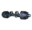
A trailer axle is a device that supports all or part of the vertical load of the trailer while moving (wheel rotation) and bears various external forces in other directions to ensure the normal driving of the trailer. As shown in Figure 1 below.

Figure 1. Trailer/semi-trailer axle
A axle is one of the important parts of a trailer, It is mainly introduced from the following aspects:
1. Technical standards of axles
(1) The technical standard of axles assembly shall comply with China transportation industry standard JT / T475-2020.
(2) The axle welding standard shall comply with the China machinery industry standard JB / T5000.3-2018.
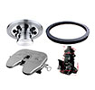
2. The composition of a trailer axle
A trailer axle is mainly composed of the following four assemblies: a axle body assembly, a camshaft assembly, a braking assembly and a wheel end assembly.

Figure 2. Schematic diagram of axle composition
It mainly includes: an axle tube, brake base plates, air chamber supports and camshaft supports, etc.
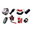
(2) Camshaft assembly
It mainly includes: camshafts, slack adjusters and a camshaft repair kit, etc.
(3) Brake assembly
It mainly includes: brake shoes, brake linings, a brake shoe accessories package, etc.
(4) Wheel end assembly
It mainly includes: hubs, brake drums, oil seals, bearings, axle nuts, and hub covers, etc.
3. Classification of axles
According to the structures of the axle, it is usually divided into the following four types:
(1) Inboard brake drum axle series:
As shown in Figure 3 below. The flange surface of the axle brake drum is located on the inner side of the hub flange surface. For the inboard axles, when maintaining and replacing the parts of the braking system, it is necessary to screw the cover and remove the bearing locknut, so that the tires, wheel hubs, brake drums and bearings can be removed together for maintenance and replacement.

Figure 3.Intboard brake drum axle for a semi-trailer
(2) Outboard brake drum axle series:
As shown in Figure 4 below. The flange surface of the axle brake drum is located outside the flange surface of the hub. For the outboard axles, when maintaining and replacing brake system parts, it is only necessary to unscrew all wheel nuts and remove tires and brake drums.
![]()

Figure 4.Outboard brake drum axle for a semi-trailer
(2) Spoke wheel hub series axle
As shown in Figure 4 below. The axle replaces the common wheel hubs with five spoke wheel hubs, six spoke wheel hubs, eight spoke wheel hubs and ten spoke wheel hubs, and matched with demountable wheel rims and spacers.
![]()

Figure 5. Spoke type axle for a semi-trailer
As shown in Figure 6 below. Compared with the drum axle, the overall structure of the axle is simpler, the braking friction surface is directly exposed to the air, the heat dissipation is better, and the phenomenon of heat recession is effectively avoided. The brake discs bear compressive stress on both sides, and have better crack resistance under continuous braking. The braking force of the left and right wheels is more average, and the response speed of the braking system is faster, which improves the safety of the vehicle.
![]()

Figure 6. Disc brake type axle for semi-trailer
4. Selection of axles
The following aspects need to be considered when selecting a axle:
(1) Axle styles
Trailer axles have usually two styles: American axles and European axles.
(2) Rated axle load
The rated axle load of the trailer axle is usually 8 tons, 10 tons, 11.5 tons, 12 tons, 13 tons, 14 tons, 16 tons, 18 tons and 20 tons.
(3) Specifications of axle tube
There are usually two types of trailer axle tubes: square tubes and round tubes: square tubes usually have 150x150mm, 127x127mm and 120x120mm, and round tubes usually have Φ127mm and Φ146mm.
(4) Specifications of axle brake
The specifications of trailer axle braking are related to the rated load of the axle,
It usually have following specifications: 311x190mm, 381x220mm, 420x180mm, 420x200mm and 420x220mm.
As shown in Figure 7 below. The wheel track is the distance between the centers of the two tires on the left and right sides of the axle. It is the core parameter of the axle. The wheel track of trailer axle usually has 1816mm, 1820mm, 1840mm, 1850mm, 1968mm, 2050mm, 2160mm, etc. And the wheel track can be adjusted according to the trailer design requirements.
![]()

Figure 7. Schematic diagram of axle parameters
(6) Distance of two brake chambers
As shown in Figure 7 above. The center distance of the brake chambers is the distance between the centers of the two chamber brackets, which is determined by the length of the camshafts, usually 354mm, 370mm, 390mm, etc. while the wheel track is same. The external dimensions of the brake chamber and the installation requirements determine the minimum distance between the centers of the brake chambers 223mm, otherwise it will affect the installation of the brake chambers.
(7)Matching parameters of wheel hub, wheel rim and wheel bolts
1)Matching parameters of wheel hub and wheel rim
As shown in Table 1 below. Matching parameters of axle hubs and wheel rims, which commonly used in a trailer axle.

Table 1. Coordination parameters of wheel hubs and wheel rims
2)Bolt hole parameters of wheel rim disc
As shown in Figure 8 below. Three common parameters of wheel disc bolt holes.
![]()

Figure 8. Common bolt hole parameters
3) Selection of wheel bolts
As shown in Figure 9 below. The correct selection of wheel bolts.
![]()

Figure 9. Selection of wheel bolt
5. Installation of axles (on trailers)
The correct installation of the axle can make the axle give full play to the best service performance, and the following requirements shall be followed during axle installation.
(1) Assembly direction of axle
As shown in Figure 10 below. The brake chamber and the slack adjuster are in the upward direction.
![]()

Figure 10. Assembly direction of a trailer axle
(2) Welding of upper or lower support plates and an axle
Because the position of the upper and lower support plates is the point of the maximum bending moment and stress concentration area of the axle, if the welding method of the support plates and the axle is incorrect or excessive weld seams will increase the possibility of axle fracture. Before welding, the support plates must fits closely with the shaft tube.
1) Welding requirements of upper or lower support plates and a square tube
As shown in Figure 11 below. There must not be any weld seams or weld spotsat the joints A, B, C, and D of the upper and lower support plates and the axle, otherwise it is easy to cause fatigue fracture of the axle tube and shorten the axle service life.
![]()

Figure 11. Welding instructions for the upper and lower support plates of a square tube
2) Welding requirements of support seats and a round tube
As shown in Figure 12 below. There shall be no weld seams or weld spots on both sides of the mating surfaces between the support seat and the axle! Otherwise, fatigue fracture of the axle tube is easy to occur, and the service life is shortened.![]()

Figure 12. Welding instructions for the upper and lower support plates of a round tube
6. Precautions for use of axles
(1) Check the tightness of the wheel nuts
As shown in Figure 13 below. After a new trailer is driven for the first time or for the first time with a heavy load and each time the wheels are replaced, the tightening of the wheel nuts must be checked and ensure that the specified torque is reached.
![]()

Figure 13.Tightening wheel bolts
As shown in Figure 14 below. The initial installation angle of the slack adjuster is 100 ~ 105 °, and the optimal braking angle is 90 °. It is recommended to adjust every 15 ~ 30 days or 5000 ~ 10000 km according to the service conditions.![]()

Figure 14. Schematic diagram of adjusting a slack adjuster
(3) Check the brake shoe and brake lining
As shown in Figure 15 below. Every month or 10,000 kilometers, check whether the brake lining is worn to the limit step position and whether the brake lining is loose through the observation hole on the dust cover.
![]()

Figure 15.Brake lining inspection
(4) Check brake drums
Check brake drums regularly every 3 months or according to the usage to eliminate potential safety hazards. When the brake drum wear exceeds the wear warning line or the friction surface has continuous cracks, the brake drum should be replaced in time. After prolonged or long-distance braking, rapid water cooling is prohibited.
(5) Check the hub bearing clearance
It is recommended to check the wheel hub bearing clearance frequently, which must be checked within three months for new trailer. The operation method is shown in Figure 16 below.
1) Lift the axle until the tire is off the ground, insert two crowbars between the tire and the ground, and check whether the hub bearing clearance is abnormal.
2) Turn the wheel in both directions (clockwise and counterclockwise) to check whether the noise increases with the increase of rotation speed.
![]()
Figure 16. Inspection of wheel hub bearing clearance
7. Lubrication of axles
In order to ensure the normal operation of a axle, it is necessary to regularly refill special grease to the relevant parts. It mainly involves the following 6 parts, as shown in Figure 17 below:
![]()

Figure 17. Axle lubrication position
(1) Camshaft bushings, spherical bearings and slack adjusters
As shown in ① ② ③ in Figure 18 below:
Suggestion: fill lubricating grease every quarter or after repair and maintenance.
Method: fill grease until there is grease overflow around.
Figure 18. Lubrication positions of camshaft bushes, spherical bearings, and slack adjusters
(2) Tapered roller bearings
As shown in ④ in Figure 19 below:
Suggestion: refill special grease every half a year or after replacing the brake shoes, brake linings and wheel hubs (it can be advanced according to the actual situation).
Method: thoroughly clean the bearing and check whether the bearing has defects such as peeling and wear. In case of damage, replace the bearing and fill it with sufficient grease.
![]()

Figure 19. Lubrication position of tapered roller bearing
(3) Hub cavity
As shown in ⑤ in Figure 20 below:
Suggestion: refill special grease every six months or after maintenance and replacement of wheel hubs (it can be advanced according to actual situation)
Method: thoroughly clean the inner cavity of the wheel hub and refill an appropriate amount of grease.
![]()

Figure 20. Lubrication position of hub cavity
8. Maintenance and service cycle of axles
The routine maintenance and service cycle of axles is shown in Table 3 below.
Table 3. Axle maintenance schedule
9. Troubleshooting of axles
Troubleshooting table-problems, causes and troubleshooting methods are shown in Table 4 below:
Table 4. Axle troubleshooting table-problems, causes and troubleshooting methods
Compiled by WONDEE Autoparts