Views: 0 Author: Wondee Autoparts Publish Time: 2022-01-14 Origin: Wondee Autoparts


1. The composition of an air suspension
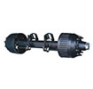
1.1 Composition of single axle lifting air suspension system
As shown in Figure 1 below. It mainly consists of the following 7 parts:
1) Air linker bracket assembly
2) Lift airbag assembly
3) Air linker assembly
4) Shock absorber assembly
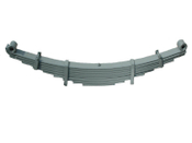
5) Load-carrying airbag assembly
The matching axle tube section types are 150x150 square tube, 127x127 square tube and Φ127 round tube, the loading capacity of axle load include 8 tons, 9 tons, 10 tons, 11.5 tons, 12 tons and 13 tons.
![]()

(Figure 1. Schematic diagram of lifting trailer air suspension)
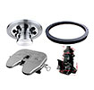
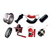
1.2 Explosion diagram of single axle lifting air suspension
As shown in Figure 2 below:
![]()

(Figure 2. Explosion diagram of single axle lifting air suspension)
1.3 List of components for single axle lifting air suspension
SN | Descreptions | Qty |
1 | 1 | |
2 | Upper axle seat assembly (right) | 1 |
3 | Lower axle seat assemblies | 2 |
4 | U-bolts | 4 |
5 | 2 | |
6 | Hexagon nuts | 8 |
7 | Airbag mounting plates (upper) | 2 |
8 | 2 | |
9 | 1 | |
10 | 4 | |
11 | 2 | |
12 | Lifting air bags assembly | 2 |
13 | 1 | |
14 | Air linker bracket assembly(right) | 1 |
15 | 2 | |
16 | 4 | |
17 | 2 | |
18 | 4 | |
19 | 2 | |
Z-type air linker assemblies | 2 | |
21 | 1 | |
22 | 1 | |
23 | 1 | |
24 | Upper support assembly of lifting air bag(right) | 1 |
25 | Wear resistant bushings | 4 |
26 | Wear resistant steel bushings | 4 |
2 | ||
28 | 2 | |
29 | Hexagon head bolts - fine thread | 2 |
30 | Hexagon lock nuts | 4 |
31 | Large washers | 8 |
32 | 1 |
2. Equipment, tools and documents required for installation
2.1 Requirements for welding location
The welding location must be clean and free from moisture, paint and oil stain. When the ambient temperature is lower than 15 ℃, the work pieces shall be preheated.
2.2 Welding equipment and tools
For all welding, CO2 gas shielded welding should be used, and the welding voltage and welding current should be determined after on-site debugging.
2.3 Torque wrench (Max torque not less than 1300N•m)
2.4 Tape measures or scales
2.5 Vernier calipers
2.6 Crane or lifting device
2.7 Grinders (handheld)
2.8 Compressed air supply device
2.9 Air wrench
2.10 Air hose and fittings, etc.
2.11 Axle positioning device
2.12 Air suspension assembly drawing, parts drawings, and air circuit system diagram and installation drawing of the trailer
3. Inspection before installation
3.1 Check whether the air suspension parameters match the technical requirements of the trailer design.
3.2 Check whether the number of parts of the air suspension is correct.
4. Installation guide process
4.1 Assembling the axle and air linker
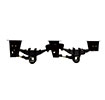
4.1.1 As shown in Figure 3, firstly, weld the upper and lower supports of the axle to the corresponding positions of the axle according to the dimensions of the assembly drawing to ensure that the dimension L tolerance is within ±1mm, and L1=L2, and the tolerance is within ±0.5mm.
![]()

(Figure 3. Welding the axle supports)
4.1.2 As shown in Figure 4 below. Use the 2 U-bolts to install the air linker and pressure plate on the axle. Refer to the air suspension assembly drawing for the specific installation location and dimensions.
Firstly, pre-tighten the U-bolts with a pre-tightening force between 150Nm and 200Nm. Then adjust the center distances L and L' of the air linkers to ensure that the difference between the diagonals A and B is within ±2mm .
![]()
![]()

(Figure 4. Installation of air linkers)
4.1.3 Tighten the U-bolts according to the torque requirements of the general assembly drawing.
Note: Do not tighten at one time, use the diagonal method to tighten each nut step by step.
4.2 Welding the air linker bracket, the upper bracket of the load-carrying air bag on the chassis
4.2.1 According to the air suspension assembly drawing, firstly determine the welding positions of the air linker brackets (left and right) and the upper brackets (left and right) of the airbag, secondly draw positioning lines for welding on the lower wing plate of the chassis, , thirdly spot-weld the brackets, al last measure whether the relevant dimensions meet the design requirements, otherwise, re-install.
4.2.2 As shown in Figure 5 below, measure A2+B2 in the process of adjusting the position of the brackets to ensure that the tolerances of a1 and a2, b1 and b2 are within±2mm.
A1: Lateral center distance of the left and right air linker brackets.
B1: Lateral center distance of the brackets on the load-carrying airbag.
A2: The vertical distance between the center hole of the air linker bracket fixing bolt and the center line of the axle.
B2: The vertical distance between the upper bracket center of the load-carrying airbag and the centerline of the axle.
a1 and a2: the diagonal distances (see Figure 5).
b1 and b2: the diagonal distance (see Figure 5).
![]()
![]()

(Figure 5.Positioningof brackets)
4.2.3 As shown in Figure 6. Weld the air linker brackets.
It is required that the start line segment 12mm and the end line segment 12mm should not be welded.
The welding of the brackets of the load-carrying airbags has the same requirements
![]()

(Figure 6. Welding requirements of air linker brackets)
4.2.4 Reinforce the chassis as shown in Figure 7 below. It can also be changed to other methods of strengthening according to the specific conditions of the trailer chassis.
![]()

(Figure 7. Frame reinforcement)
4.3Install the air linker assembly and air linker bracket assembly
4.3.1 Use a temporary frame to support the entire semi-trailer chassis to a height that is convenient for installation, and ensure that the support is firm.
4.3.2 Install the lifting airbag assembly as shown in Figure 8.
![]()

(Figure 8.Assembling of the Lifting Air Bag Assembly)
4.3.3 Install the relevant parts as shown in Figure 9, and then connect them with bolts. The locking torque is: 200NM~300NM.
(Figure 9. Installing the air linker assembly)
4.4 Install the lower mounting plate of the load-carrying airbag
As shown in Figure 10 below, fix the lower mounting plate of the load-carrying airbag, the connecting beam of the air linker and the support sleeves with bolts and nuts, and tighten them according to the designed torque.
![]()

(Figure 10. Installation of mounting Plate of the load-carrying Airbag)
4.5 Installation of shock absorbers and load-carrying airbags
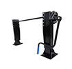
4.5.1 Install shock absorbers
。
As shown in Figure 11 below. Use bolts to fix the two ends of the shock absorber to the air linker bracket and the upper support of the axle respectively.
Attention: 1). Just screw the nuts, no need to tighten up.
2). The shock absorber must be oriented as shown.
![]()

(Figure 11. Installation of shock absorber)
4.5.2 Install load-carrying airbags
Install the load-carrying airbags on the upper and lower supports with bolts. Tightening torque according to design requirements.
4.6 Install the pneumatic circuit that controls the height of the axle
Install the pneumatic circuit according to the construction drawings as shown in Figure 11 below.
![]()

(Figure 11. Axle height control pneumatic circuit)
Note: The LSV leveling connecting rod is usually installed on the axle of the mechanical suspension adjacent to the air suspension, and the LSV is installed on the chassis above it. As shown in Figure 12 below.![]()

(Figure 12. Installation schematic diagram of pneumatic circuit)
4.7 Height adjustment of the air suspension
After the above pneumatic circuit is installed, the air bags are inflated, and the suspension height is adjusted by adjusting the angle of the leveling rod of the load-sensing valve. After the suspension height is adjusted to the design range, fix the LSV leveling rod.
Note: When the air bag lifting height reaches the suspension design height (the vehicle is running normally), the LSV leveling rod should be kept in a horizontal position and at 90° to the connecting rod. As shown in Figure 13 below.![]()

(Figure 13. Adjustment and Fixing of Load Sensing Valve)
4.8 Locking bolts
After the adjustment is completed, tighten the air linker fixing bolts and the shock absorber upper and lower fixing bolts according to the design torque.
4.9 Install the pneumatic brake system according to the design requirements (omitted here)
5. Other regulations
Execute in accordance with the relevant standards and regulations of the vehicle manufacturer.
Compiled by WONDEE Autoparts
2022-1-14