
Views: 0 Author: Wondee Autoparts Publish Time: 2022-08-05 Origin: Wondee Autoparts


Introduction of fuel tankers(Part 2)
- use and maintenance
1. Preparation before the new vehicles using
(1) Clean the tank with gasoline (pay attention to the ventilation in the tank during operation) or compressed air before use.
(2) Open the drain outlet or valve to clean the tank.
(3) Check whether the grounding rubber tape touches the floor.
(4) Check whether the valves at each oil drain port are closed.
2. Use of fuel transportation vehicles
(1) Fill with oil.
Connect the earth wire to the static conductive connecting plate of the oil tanker, open the manhole cover above the tank, insert the oil delivery pipe into the tank, and then fill the oil. The oil loading volume should be limited to the rated capacity of the oil tanker, and overload is not allowed.
(2) Unloading oil.
Connect the oil delivery pipe in the vehicle's pipe box with the oil drain port, and turn the handle of the oil drain valve to the open position to unload the oil.
(1) In addition to completing the first " Preparation before the new vehicles using " before the refueling vehicles using, the oil level height of the lubricating oil in the speed increase box of the oil pump and the gearbox of the vehicle should also be checked. If it is insufficient, it should be filled. At the same time, check whether there is oil in the pump. Otherwise, fill about 10 liters of oil first.
(2) The items that should be checked before using the power take-off are the same as above step (1).
Put the shift lever in neutral, the power take-off in the disengaged position, then step down the clutch, start the engine, put the power take-off in the engaged position, then release the clutch pedal, and gradually step down the accelerator pedal to realize the functions of the refueling vehicle.
After the power take-off is combined, pay attention to the operation of the power take-off and the transmission system. If there is any abnormal response, disconnect the power take-off immediately and find out the cause. The power take-off has been adjusted in factory. Users should not disassemble it at will during use. When the power take-off breaks down, it is not allowed to reduce or increase the gasket between the power take-off and the gearbox at will after removal and repair. Otherwise, it is easy to cause damage to the power take-off or increase noise, and also affect the transmission of power.
(3) The use and operation instructions of the refueling vehicle pipeline system (the structure 1, as shown in Figure 1 below) are as follows:
(1)Figure 1. Refueling vehicle pipeline system (1)
1. Tank, 2, 9. Three-way ball valve 3. Primary filter 4. Vacuum gauge 5. Oil pump 6. Flow gauge 7. Fine filter 8. Pressure gauge
a. Self-flow oil unloading
Turn the color dot of No. 2 ball valve to port C, and connect ports a and b to realize the self flow oil drainage from Port A
b. Fill the oil in the tank into other containers through filtration.
b. Turn the color dot of No.2 ball valve to port B, connect ports a and c, turn the color dot of No.9 ball valve to port e, connect ports d and f, and turn on the oil pump. Then the oil in the tank can be filled from the oil drain port C to other containers through the oil pump of the vehicle. The oil flow is: tank body → ports a and c of No. 2 ball valve → primary filter → oil pump → ports d and f of No. 9 ball valve → oil drain port C.
c. Fill the oil in the tank into other containers through filtration and metering.
c. Turn the color dot of No. 2 ball valve to port b, connect ports a and c, turn the color dot of No. 9 ball valve to port f, connect ports d and e, and turn on the oil pump to fill the oil in the tank through the oil drain port B to other containers with filtration and metering. The oil flow is: tank → ports a and c of No. 2 ball valve → primary filter → oil pump → ports d and e of No. 9 ball valve → fine filter → flow gauge → oil drain port B.
d. Suck the oil into the tank of vehicle from the container that meets the oil absorption conditions.
Turn the color dot of No. 2 ball valve to port a, connect ports b and c, and turn the color dot of No. 9 ball valve to port e, connect ports d and f, connect the oil delivery hose from the oil drain port c, and put the other end of the oil delivery hose into the tank from the small cover. The oil flow is : oil supply container (oil depot) → drain port a→ ports b and c of No. 2 ball valve → primary filter → oil pump → ports d and f of No. 9 ball valve → drain port C→ oil delivery hose → tank body of the vehicle.
When it is necessary to measure, the color dot of No. 9 ball valve turns to port f, connects ports d and e, connects the oil delivery hose from the drain port B, and puts the other end of the oil delivery hose into the tank from the small cover. The oil flow is: oil supply container (oil depot) → oil drain a → ports b and c of No. 2 ball valve → oil pump → ports d and e of No. 9 ball valve → fine filter → flow gauge → oil drain B→ oil delivery hose → tank body.
e. Used as a mobile oil pumping station.
The operation when used as a mobile oil pumping station is the same as article d.
f. Circulating and mixing the oil in the tank
The operation of circulating and mixing the oil in the tank is the same as that in article c. only connect the oil delivery hose to the corresponding oil outlet and put the other end of the oil delivery hose into the tank from the small cover.
(4) The use and operation instructions of the refueling vehicles pipeline system (the structure 2, as shown in Figure 2 below) are as follows:![]()
")
(1. Tank, 2, 9, 10. Three-way ball valve, 3. Primary filter, 4. Vacuum gauge, 5. Oil pump, 6. Flow gauge, 7. Fine filter, 8. Pressure gauge, A, B, C - Oil drain port connector)
(2)Figure 2. Refueling vehicle pipeline system (2)
Turn the color dot of No. 10 ball valve to port j and connect ports h and g, which is the same as the pipeline system of the structure 1, so as to complete the operation of various functions.
a. Circulating and mixing the oil in the tank
Turn the color dot of No. 10 ball valve to port g, connect ports h and j, and then the oil in the tank can be mixed circularly.
b. Suck the oil into the tank of vehicle from the container that meets the oil absorption conditions.
When the oil in the container that meets the oil absorption conditions is sucked into the tank, the color point of No. 2 ball valve should be turned to port a, and the oil can be directly sucked into the tank from the pipeline system by connecting the oil supply container and the oil drain port a with the oil delivery hose. At this time, the oil flow is: oil supply container → oil drain port A → ports b and c of No. 2 ball valve → primary filter → oil pump → ports h and j of No. 10 ball valve → tank.
(5) In the pipeline system of both structures, the device with refueling hose and oil gun can be optional. The hose connector is connected to the oil drain port C. The color dot of No. 9 ball valve is turned to port f, and ports d and e are connected. The other operations are the same as article (3) and article (4).
4. Maintenance and safety of fuel tanker
(1) In order to ensure the cleanness of the oil in the tank, the oil tank should be cleaned regularly and the dirt should be discharged from the drain outlet.
(2) In order to prevent fire, it is not allowed to drive the vehicle when the fire muffler or fire cap fails, the pipeline system or tank body leaks, the grounding rubber tape fails, and the earth wire is not connected.
(3) When the sedimentation basin of tank body is frozen due to accumulated water, it is not allowed to thaw with fire. The vehicle should be driven to the greenhouse or heated with steam to thaw.
(4) It is strictly forbidden to knock on the oil tank truck with metal objects to avoid sparks.
(5) When working inside the oil tank, the oil vapor in the tank should be drained, there should be personnel outside the tank for emergency support, and the personnel working in the tank should wear gas masks. At the same time, fresh air should be continuously delivered to the tank.
(6) In the process of loading and unloading fuel, even if it works for a short time, it is not allowed to turn off the tractor engine, so as to drive away from the site or oil depot immediately in case of emergency.
(7) When the refueling vehicle is using the refueling system, you should always check whether there is any abnormal sound in the refueling system. Observe the indications of the pressure gauge and vacuum gauge at any time. If the engine runs at medium speed for 4 minutes and still no oil is pumped out, stop working immediately, check to find out the cause, and work only after the fault is eliminated.
(8) Drivers and passengers must be familiar with the use of fire extinguishers, and should maintain and replace fire extinguishers in time (refer to the fire extinguisher instruction manual for details).
(9) In case of oil leakage of tank and pipeline, It is absolutely not allowed to use electric and gas to weld without cleaning. The correct way is to drain the oil and fill the tank with alkaline water. After driving 30-50km on the bumpy road, drain all the alkaline water and wash the tank with steam for several times. Open the manhole cover of the tank, open all valves, place it for a period of time, and drive the vehicle into an open place before welding. The welding time should be as short as possible. If you are unsure, please contact the manufacturer.
(10) In order to prolong the service life of the vehicle, the vehicle shall be loaded according to the rated load capacity, which shall not exceed the maximum total mass of the original vehicle.
(11) This product is a special vehicle for transporting fuel and should be used under the following conditions: The grade of driving road shall not be lower than grade IV road surface; The ambient temperature is -40 ℃ ~40 ℃; The relative humidity of the air is not more than 95% (25 ℃).
5. Daily routine inspection
In order to prevent accidents and ensure driving safety, it is necessary to carefully check the vehicle every day to understand the situation of the vehicle. and the inspection about the vehicle is never omitted.
(1) Place the vehicle on a level ground and park it.
(2) When the vehicle was abnormal and has been repaired, recheck whether there is no problem.
(3) Drain the condensed water in the air tank after using the vehicle every day, and check whether the brake pipeline is loose, damaged, leakage, whether the parking brake is normal.
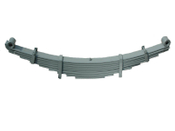
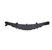
(4) Check the leaf spring and the fastening of the nut (Leaf spring U-bolt nut, leaf spring limit nut, balance arm nut, thrust rod nut, etc).
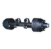
(5) Whether the landing gear is normal (Fuel transportation vehicle).
(6) Turn on the switch of each lamp and check whether the corresponding lamps are on.
(7) Check whether the tire pressure and tread are normal, and whether there are foreign bodies and damage on the tread. If there is any, deal with it in time.
(8) Drive the vehicle after normal inspection, and start driving at the speed of 5-10km/h for trial operation inspection.
By WONDEE Autoparts
2022-8-5


")
