Views: 0 Author: Wondee Autoparts Publish Time: 2021-12-29 Origin: Wondee Autoparts


1. Main parameters of leaf springs
As shown in Figure 1 below. The main parameters of leaf springs are:

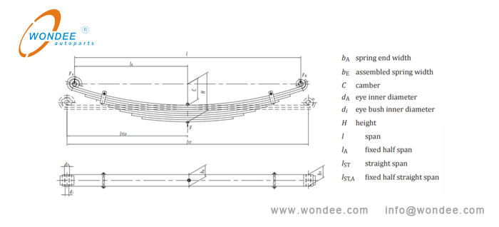
(Figure 1. Main parameters of leaf springs)
2. Main processing technology of leaf spring ends
As shown in Figure 2 below. The end processing technologies of leaf springs mainly includes the following categories:

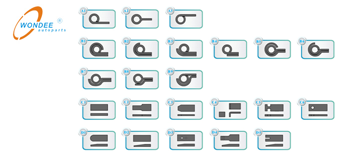
(Figure 2. Processing technologies of leaf spring ends)
3. Tools for measuring leaf springs
As shown in Figure 3 below. The following tools are mainly used in the measurement of leaf springs: a vernier caliper, a tape measure, a square ruler, a cord, a thread gauge (not commonly used), a fillet R gauge (not commonly used), a pen and papers for recording data, etc.

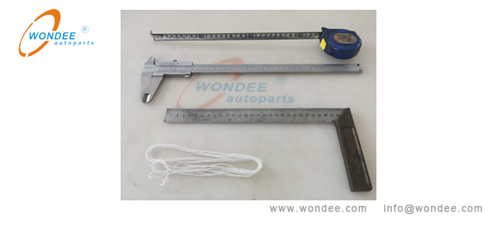
(Figure 4.Tools for measuring leaf springs)
4. Measurement of leaf spring assembly
1) Photographing and archiving
Record the identification contents and paint colors of leaf springs.
2) Measure and record the arc height (H), arc length (L) and half arc length of the leaf spring assembly
As shown in Figure 4 below. 2-3 people are required to measure with a cord and a tape measure.

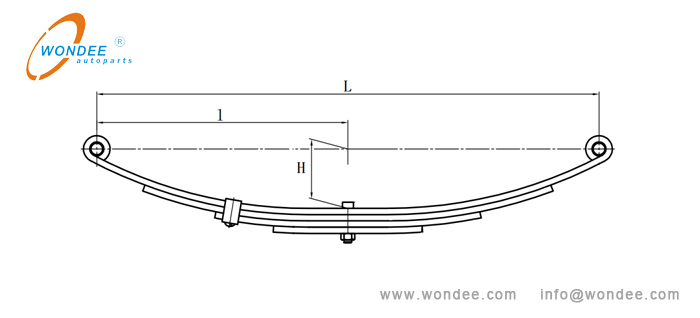
(Figure 4. Arc height and arc length of the leaf spring assembly)
3) Measure and record the parameters of the center bolt
As shown in Figure 5 below. Use a vernier caliper and a thread gauge to measure the bolt sizes (bolt head diameter and height, bolt length, etc.) and record the data. At the same time, record the position of the bolt head (on the concave or convex surface of leaf spring assembly).
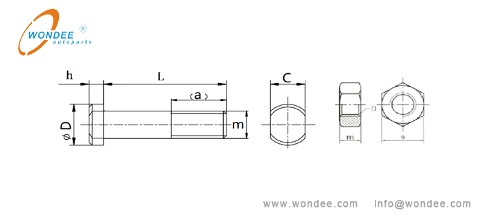
(Figure 5. Parameters of a center bolt)
4) Measure and record the clamps, clamp bolts
As shown in Figure 6 below. Measure with a vernier caliper. Record the serial number of the leaf spring sheet where the clamp is located, clamp positioning dimension (L), clamp quantity, material thickness (h) and width (b) of each clamp, clamp bolt hole distance (H), clamp bolt dimension, etc.

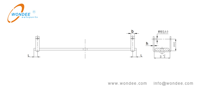
(Figure 6. Schematic diagram of a clamp)
5) Measure and record each leaf
See article 5 for details.
Note: the disassembled leaves shall be placed according to the original leaf spring assembly direction, and the placement direction shall not be changed at will.
5. Measure the single leaf
Before measurement of the single leaf, take photos and keep files, record the product color and material specification (width and thickness), and then measure the dimensional data.
1) Measurement of end trimming and corner cutting
As shown in Figure 7 below. Measure sizes b and l with a vernier caliper. Record the relevant dimensional data (b) and (l).

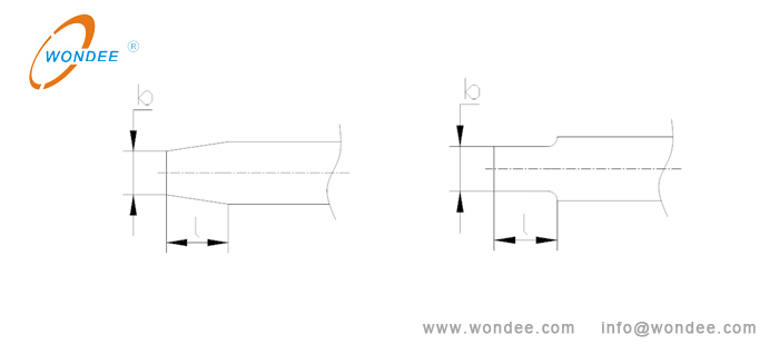
(Figure 7. Measurement of end trimming and corner cutting)
2) Measurement of end bending and compression bending
As shown in Figure 8 below. Measure with a vernier caliper and a tape measure. Record dimensional data (H, L1 or L, l and h.)

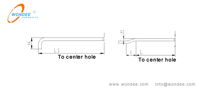
(Figure 8. Measurement of end bending and compression bending)
As shown in Figure 9 below. Measure with a vernier caliper and a tape measure. Record dimensional data (h) and (l).

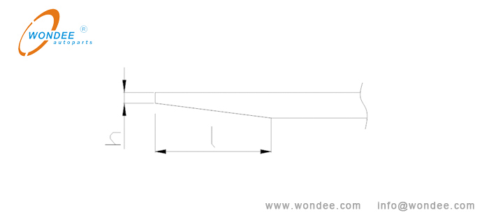
(Figure 8. Measurement of short taper)
As shown in Figure 10 below. If the short tapered leaf spring with a rib groove, use a vernier caliper and a tape measure for measurement. Record relevant dimensional data.
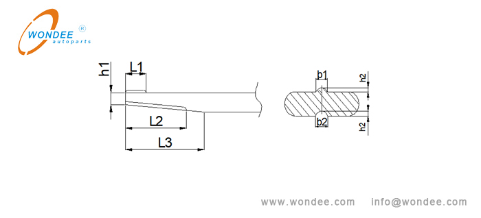

(Figure 10. Measurement of a short tapered leaf spring with a rib groove)
4) Measurement of rolled eyes
As shown in Figure 11 below. Measure with a vernier caliper and a tape measure. Record relevant dimensions. When measuring the inner diameter of the eye, pay attention to the possibility that there may be horn holes and elliptical holes in the eye. It shall be measured 3-5 times, and the average value of the minimum diameters shall prevail.

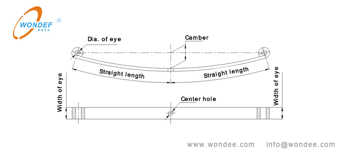
(Figure 11. Measurement of leaf spring with rolled eyes)
If the rolled eye contains bushing, use a vernier caliper to measure and record the relevant sizes and material of bushing. Common bushings are as follows:,
① Bi-metal bushings and copper bushings
Use a vernier caliper to measure the 3bushing sizes are shown in Figure 12 below:

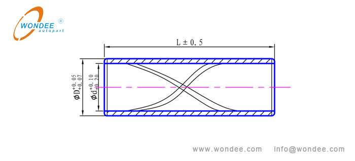
(Figure 12. Schematic diagram of copper bushing and bi-metal bushing)
② Rubber composite bushings
Use a vernier caliper to measure the related sizes of rubber composite bushing is shown in Figure 13 below:

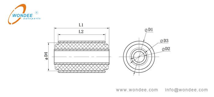
(Figure 13. Schematic diagram of rubber composite bushing)
③ Rubber composite flanging bushing
Use a vernier caliper to measure the related sizes of a rubber composite flanging bushing, as shown in Figure 14 below:

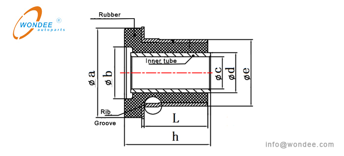
(Figure 14. Schematic diagram of rubber composite flanging bushing)
5) Measurement of wrapped eyes of a leaf
As shown in Figure 12 below. Use a cord, a tape measure and a vernier caliper to measure and record relevant data.
After measuring L2,L1 can be calculated by the formula L1 ≈ L2 - (H1 / 2 + 4). If the length sizes of the matching ear leaf is known, the leaf spring engineer can calculated the sizes L1 and L2 accordingly.If there are corner cutting and edge cutting processes, and the dimensions of corner cutting and edge cutting are measured in addition.

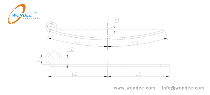
(Figure 12. Measurement of wrapped eye)
There are three main types of long tapered leaf springs: ordinary trapezoidal structure, abrupt trapezoidal structure and parabolic structure. Use a tape measure and a vernier caliper to measure and record relevant data. The measurement method is as follows:
① Ordinary trapezoidal structure
As shown in Figure 13 below. Measure and record the data with a vernier caliper and a tape measure.

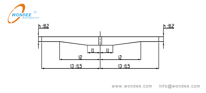
(Figure 13. Measurement of long tapered leaf spring-ordinary trapezoidal structure)
② Abrupt trapezoidal structure
As shown in Figure 14 below. Measure and record the data with a vernier caliper and a tape measure.

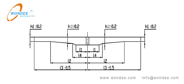
(Figure 14. Measurement of long tapered leaf spring- abrupt trapezoidal structure )
As shown in Figure 15 below. Measure and record the data with a vernier caliper and a tape measure.

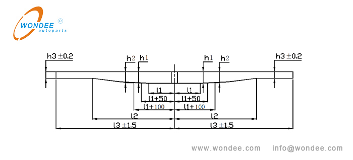
(Figure 15. Measurement of long tapered leaf spring-parabolic structure )
The measurement record table of a parabolic structure leaf spring is shown in below table.
L | L1 | L1+50 | L1+100 | L1+150 | L1+200 | L1+300 | …… | L2 | L3 |
Thickness | H | h1 | h2 | … | … | … | … | h3 | h3 |
Note: L is the distance between the center of the center bolt and the measurement point.
7) Measurement of milling edge and a flat-straight segment
As shown in Figure 16 below. Use a vernier caliper and a tape measure to measure and record relevant data.

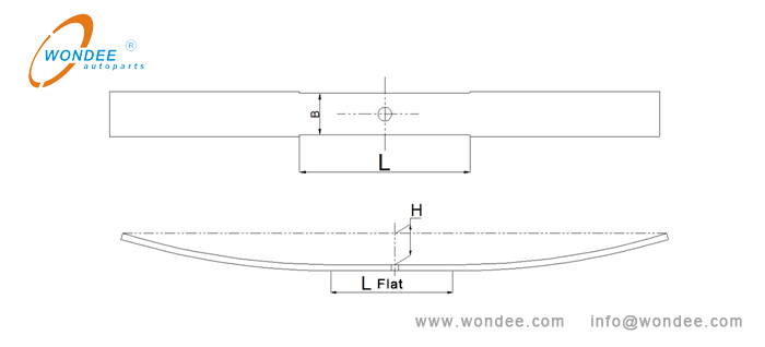
(Figure 16. Measurement of milling edge and flat-straight segment)
8) Measuring camber Hof a leaf spring with a flat-straight segment in the middle and unequal arc length on the left and right sides of the center hole
As shown in Figure 17 below. Use a cord, a tape measure and a square to measure and record relevant data(H, Hl and Hr).

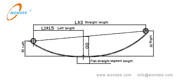
(Figure 17. Measurement of camber height of leaf spring)
9) Measurement of concave convex center hole
As shown in Figure 18 below. Use a vernier caliper to measure and record relevant data.

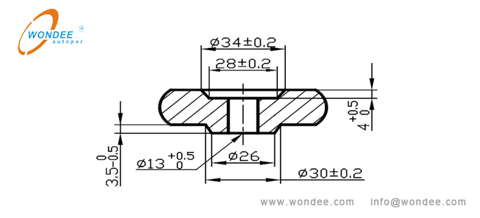
(Figure 18. Measurement of concave convex center hole)
10) Measurement of oval center hole
As shown in Figure 19 below. Use a vernier caliper to measure and record relevant data.

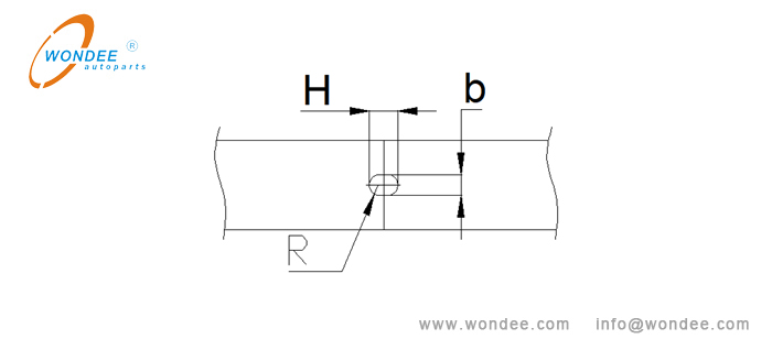
(Figure 19. Measurement of oval center hole)
Compiled by WONDEE Autoparts
2021-12-29
What Are The Most Common Semi-Trailer Parts And Their Functions?
How To Hook Up A Trailer To A Truck: A Foolproof Step-by-Step Guide
Tanker Truck Sizes: A Complete Guide (2025) – Dimensions, Types & Expert Tips
Understanding Semi-Trailer Dimensions for Efficient Equipment Transport
Differences Between Lowboy and RGN Trailers: Choosing the Right Trailer for Your Haul
Understanding Full Trailers Vs. Semi-Trailers for Car Hauling